Welding Symbols – The Breakdown
This post contains affiliate links.
Let’s get into it. Welding symbols can seem daunting at first glance. This article will show you how simple they are to read and follow.
These symbols have been developed in large by the American Welding Society. The symbols help tradesmen across the world in executing welding projects properly (and also to code). The Symbols are universal, so any job you may land during your career will be using these symbols for their blueprints.
Understanding welding symbols is crucial in terms of fabricating projects properly. Once you memorize the symbols and their meanings, your fabrication prowess will certainly improve, and you’ll be well on your way to becoming an awesome fabricator.
Engineers use these symbols to convey their designs to the welders. If welders execute the welds properly, the final product will be up to the engineers standards.
Welding Symbols
One of the most important welding symbols is the fillet weld. This weld is an extremely common practice in fabrication and field work. This symbol is characterized by a right triangle which is the lateral shape of a real fillet weld.
Fillet welds are generally performed on a 90 degree joint of 2 perpendicular pieces of metal. The diagram further down shows the different parts of a fillet weld.
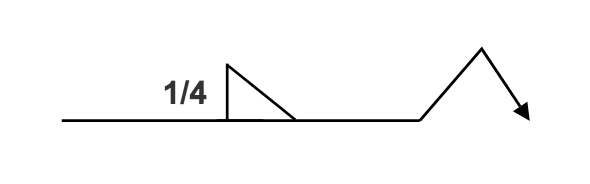
Often times, blueprints will call for particular sizes of fillet welds. As you improve your welding skills, you’ll be able to execute these different sizes based on your machine settings and travel speed. Electrode sizing also plays a part in this as well.
The diagram below these explanations shows the 5 main parts of a weld.
1. The leg of the weld is generally regarded as the size of the weld. Larger sizes will result in a wider “leg”. This often requires heavier electrodes and higher amps/volts. Structural welds usually require larger leg sizes since they are supporting more weight. Ornamental welds can usually have smaller legs, since they aren’t holding much weight (i.e. handrails, signs, etc.)
2. The root of the weld is regarded as the initial penetration that the weld gets into both metal pieces. On an “open root” pipe joint, the root pass is the first weld that joins the pipes together. The strongest root welds will have maximum penetration. This means that the weld will have a stronger resistance to cracks and breaks.
3. The face of the weld is the exterior of the weld bead that is visible to the eye. This should be visually appealing without defects. Problems such as porosity will be visible on the face of the weld. This can cause inspectors to fail the weld, as there are small holes that weaken the strength of the final bead. Defects such as this will require the welder to grind out the weld and redo it.
4. The toe of the weld is where the weld bead meets the base metal. This should be a smooth, seamless transition. If you burn in your weld too hot, this will cause undercut at the toe of the weld. Undercut is when the weld cuts into the base metal and forms an indent. This is regarded as a defect because it weakens the weld significantly.
5. The throat of the weld is the distance between the welds face to the root of the weld. This is basically measuring how deep the weld is. The throat should usually be as thick as the metal pieces you are welding together. If you’re welding 1/4″ steel, the throat depth should be at least 1/4″. Some blueprints may call for shallower or deeper throat depths, depending on the engineers calculations.
                        the visual layout of the 5 parts of the weld


Welding Symbols Chart – Check Price On AmazonÂ
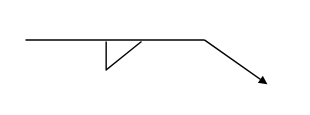
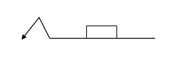
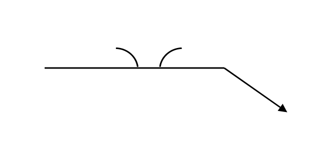
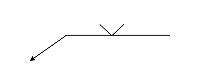
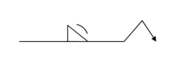
Lets jump into the actual welding symbols found in todays blueprints. The flat reference line has an arrow pointing to the joint that needs to be welded.
If the weld symbol is below the line, you must weld the side of the joint being pointed at. Additionally, if the weld symbol is above the line, the opposite side of the joint must be welded. The arrow can be drawn at many angles, but don’t read too much into this.
Different project managers will draw their arrows at many different angles. The important part is that you understand which side of the joint must be welded out.
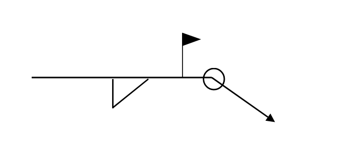
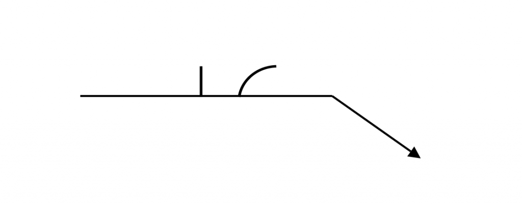
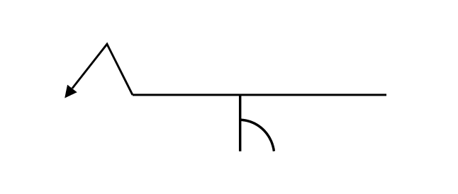
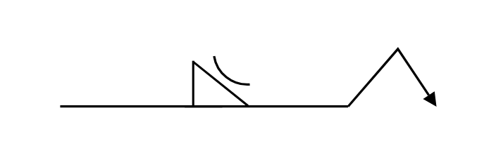
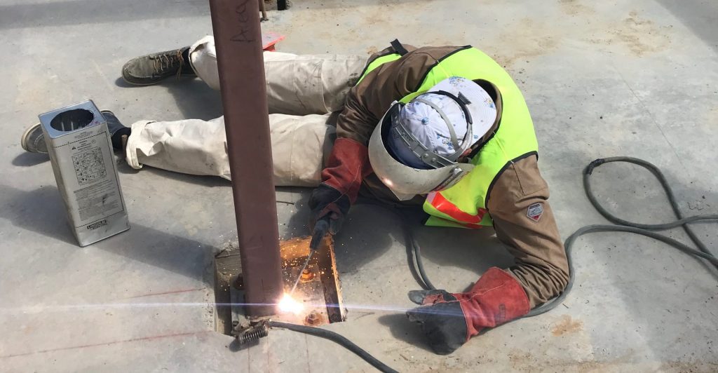
If there is a flag on the weld symbol, it means the weld must be done in the field – ie. a job site/outside. No flag symbol means it will be welded in the shop.
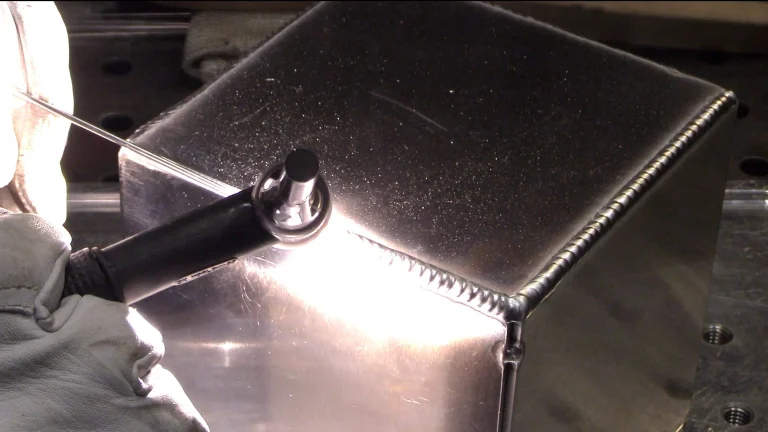
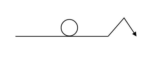
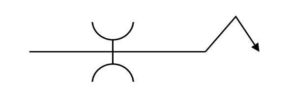
Also, welding all around a specific joint is represented by a circle at the arrow junction. Lets say you are welding a piece of pipe onto a plate – the weld will generally need to be run around the entire pipe to ensure proper fusion to the plate. The circle symbol means your weld must be ran around the entire perimeter, with no gaps at all.
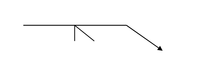
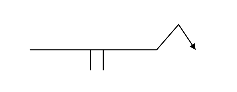
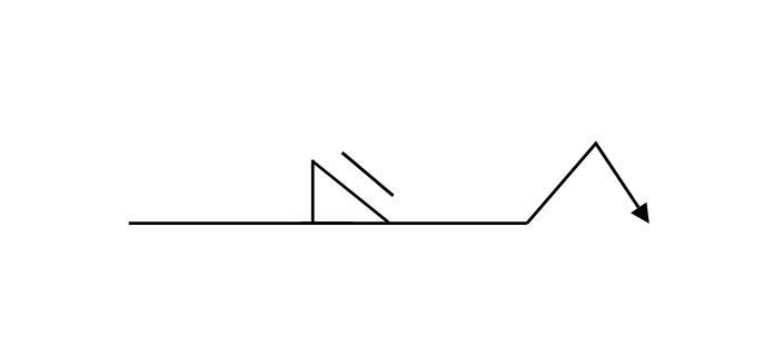
Stitch Welding Symbols
Stitch welds are characterized by a spacing between each weld. This spacing can also be referred to as “pitch”. These stitches are common when welding on a long piece of material, because a continuous weld is not always necessary. It can cause more harm to have a long continuous weld, because warping becomes a lot more likely with that much heat input.
The more weld passes you put on a joint, the more likely the steel is to warp. This heating/cooling pattern causes metal to bend and shrink.
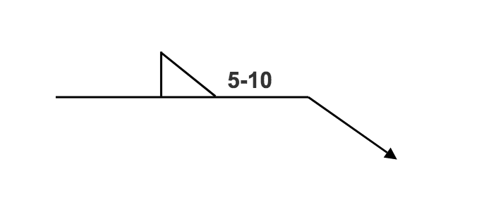
Let’s say you have a 10 foot piece of angle being welded onto a plate. The shop calls for 5 inch welds with spacings of 10 inches. The length of your weld is always stated first. The spacing of your welds will be stated second. So, to the right of your weld symbol, you will see “5-10”.
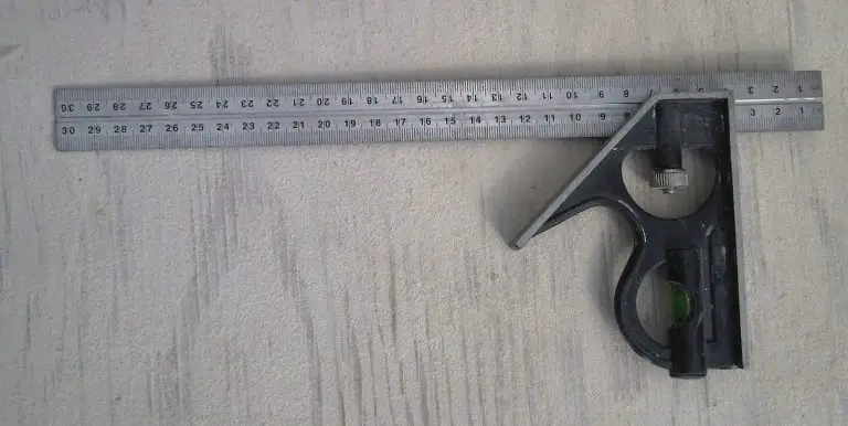
Keep in mind that the spacing of welds is measured center to center. This means that if you take your tape measure and start at the center of your first 5 inch weld, the 10 inch mark would fall on the exact center of your second weld. Although the center to center spacing is standard procedure, not all fabrication shops will follow this guideline.
Some engineers will actually put a 10 inch spacing between the welds start and stop points. Make sure to specify this before you begin the fabrication process.
Plug/Slot Welds
A plug weld is when a hole in one piece of material allows a weld to fuse it to another piece of material. Think of a circular hole drilled to attach some steel pieces – instead of using any hardware or bolts, we just weld the inside of the hole to attach the two pieces of material.
These are often ground flush afterwards, so you can’t tell how the pieces were attached together in the first place. A slot weld is similar, but it is an elongated oval hole allowing for more fusion of the two pieces of metals.
Spot Welds/Projection Welds
Spot welds are used to join sheet metal by using very fine opposing electrodes that fuse the sheets together. This is typically done in huge production runs of manufactured items where sheet metal is the primary material.
Projection welding is similar, but it can weld thicker sheet metals. This is due to the flat, wide profile of projection electrodes, as well as a higher electrical current than spot welding.
Spot/projection welding machines can only accomplish their intended task of fusing two pieces of thinner metal. You can’t use these machines for much else than that. You generally won’t see a spot welding machine in a fabrication shop.

Groove Welding Symbols
Groove welds involve quite a few welding symbols. The good news is that these symbols show the exact shape of the groove being welded, so you can get an idea for what it should look like before you begin.
These welds are usually performed on two pieces of material butted up against each other. Groove welds are characterized by a trench in between two pieces of material that must be filled. Let’s go over the groove weld symbols.

Bevel Groove Welds
When two pieces of material butt up against each other, there isn’t room for a weld to penetrate sufficiently. Often times, a bevel is placed on one piece of metal. This allows more filler metal to be deposited during the welding process. This ensures joint strength and is common practice among many welding applications.
Using an angle grinder is a great way to add a quick bevel on a piece of material. Hard wheels and rougher resin disc attachments can place a nice, smooth bevel within a matter of seconds.
For the bevel groove weld, one piece of material stays unaltered, while the other has a 45 degree bevel placed on the edge. This is probably the most simple groove weld, and it is a great joint for beginners to practice.
Flare V Groove Welds
When you weld two pieces of material that are both rounded, you are presented with a curvy “V” shape. A good example of this groove is two pieces of parallel pipe that are touching each other.
These Flare V grooves usually result in a nice flat bead, but can be hard to accomplish with TIG welding. This is because having enough tungsten stick out and proper gas flow means you must have upgraded TIG equipment, and tons of practice under your belt.
I usually prefer to weld Flare V joints with MIG or Stick processes because I can just get in there easier and faster.
The Flare V style joints are less common, I have only done a few during my welding career.
Flare Bevel Groove Welds
These are done when welding a round piece of material to a parallel flat piece of material. Think of the flare bevel groove as half of a flare V groove mentioned above. Pipe running laterally along a plate will often require this weld. One piece is flat and one has a curved radius to it (most often a piece of pipe) although not always.
U Groove welds
These are done when two plates butted together each have a partial radius beveled into their edges. The result is basically a half circle when the pieces are joined. The welder must fill up this groove to adequately join the plates together. Due to the odd shape, this is less common but is still good to understand.
Square Groove Welds
This is when there is a square gap between two pieces of material. Let’s say two plates are almost butted up together, but there is an 1/8″ gap. You must fill this square gap with your filler metal. This is common when welding schools want students to get a feel for open root tests. Students will practice this 1G welding position by learning to fill a small gap for adequate penetration.

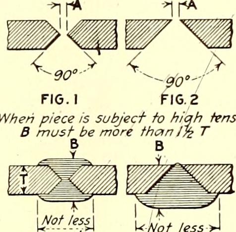
V Groove Welds
This is most common on plate tests through the AWS. Two plates have identical bevels and the resulting groove must be filled. These are considered some of the strongest joints; because a passed bend test proves that the weld is just as strong as the steel itself. A common angle for these V grooves is 37.5 degrees on each plate. Butted up against each other, these will make a V Shape.
A “landing” is often placed on the sharp edges after the bevel has been cut. The sharp edges will be ground down to allow the filler metal to fuse properly when the welder is performing the open root. This is common and usually mandatory for open root styled tests, and the landings are often 1/16″ or 1/8″.
Landings are extremely important for pipe welding. If you don’t place a landing on the pipes, you will blow through the steel while performing the open root pass. This will result in a failed test. The landing absorbs heat, which is super beneficial.
J Groove Welds
A J groove weld is simply half of a U groove. Two plates are butted up together. In this case, one plate has no bevel and the other has 1/4 radius on it. These are less common, but have been in the AWS standards for many years.
Convex, Concave and Flat Welds
These designations tell you what profile your finished weld should have. Some inspectors have preferences in the profile of final welds. Also, Some shops have standards for the looks they prefer.
Getting these profiles in your welds consistently can require an advanced knowledge of machine settings as well as lots of practice. The symbols for these are really simple, detailed below.
Different weaving patterns can help achieve these flat, convex or concave welds. Once you have been welding for some time, you’ll find that you can manipulate your puddle to achieve these profiles.
Most shops won’t call for these specific profiles unless a project really requires it. Usually inspectors are more concerned with the size of your weld and the consistency, rather than the profile of the finished bead.
Sometimes you will have to grind the weld flat to produce a minimal bead. If you place a bevel on the steel before you weld it and then grind it flat, there will still be a weld that is not seen. These types of beveled welds are usually done on high end projects for interior designs. It is a way of joining metal where the actual weld is undetectable.
If you want to practice these invisible welds, simply perform a bevel groove weld and then grind the weld away with a resin disc. The metal is still welded, but you can’t see it.
Wrap Up
Although all of these welding symbols may seem confusing, you’ll memorize them easily over time. The more you see symbols in blueprints and execute what they are calling for, the easier it’ll get.
If you are job hunting for a full time welding job, having a good knowledge of these symbols will give you an advantage over other job applicants. Shop managers get frustrated by employees who don’t know their symbols. If you can read symbols, understand blueprints, and fabricate well – then a shop looking for a new welder will be lucky to have you.
My welding school had a blueprint class that was required to complete the program. Although we understood the symbols by the end of the class, it didn’t fully sink in until we practiced them by welding actual joints in the shop.
Once you start to piece together the different groove joints, you’ll gain confidence and you’ll be more prepared for future projects.